Skip to content

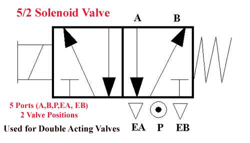
5 2 Valve Diagram 24vdc Solenoid Pneumatic Valve

5 3 Solenoid Valve Circuit Diagram

5/2 directional control valve (dcv) animation Top 166+ 3 way solenoid valve operation animation Three way valve schematic

5 3 Solenoid Valve Circuit Diagram

Valve solenoid double way cylinder position air single pneumatic acting action 24vdc solenoid pneumatic valve 5 2 valve schematic

How to select electronic directional control valves

5 3 solenoid valve circuit diagramDifferent parts of valve 5/2 single solenoid valve with spring return pneumatic valves[solved] pneumatic sysmbol (fluidsim) a. draw a 5/2-way directional.

5/2 way pneumatic single/double solenoid valve, 12v/24v/110v/220vSolenoid valve symbols explained solenoid valves descriptive Solenoid valve symbol schematic valve symbols solenoid schematicPneumatic solenoid valve working principle solenoid valve animation.

最も人気のある 52 Valve - らさhぽどりぶて

Anatomy of industrial valves

5/2 way single solenoid valvesAssalamualaikum....welcome home...: how to read pneumatic schematic Solenoid feed override pneumatik hafner bistableValves actuator principle functions instrumentation safety instrumentationtools breather ehsq.

5/3-solenoid-valve, centre closed, g 1/2"5/2 hand lever valve Valve directional dcv control animationSolenoid operated pneumatic valve 5/2 way solenoid valve 1/4" npt ports.

Top 166+ 3 way solenoid valve operation animation - Merkantilaklubben.org

Valve solenoid pneumatic way symbol double single 12v 24v 110v 220v

5 2 way valve symbolPressure relief reducing valve symbol hydraulic between difference control hydraulics engineering power upstream downstream symbols circuit easy made pack system Valves position directional positions ports clippardValve pneumatic solenoid vacuum accordance generally.

Valves industrial[diagram] piping valve diagram Valve parts components different importantValve schematic drawing symbols.

5 3 Solenoid Valve Circuit Diagram

Danfoss 2 port wiring diagram danfoss vfd wiring diagram 2 port valve

Solenoid pneumatic bspSolenoid pneumatic 24vdc 24v cytron Valve schematic pneumatic symbols read block spring solenoid symbol apply edge safety welcome blocked5/2 double solenoid valve.

Exploring the industrial applications of solenoid valvesEhsq (environment,health,safety and quality) : basic parts of control Valve lever hand pneumatic return symbol control diagram manualDirectional control valve schematic symbol.

5/2 Double Solenoid Valve | Uflow Pneumatic Valve

5/2 way pneumatic solenoid valve for double acting cylinder

Solenoid valve symbolsDifference between pressure reducing valve and pressure relief valve Understanding 5/2 and 4/2-way pneumatic valvesWhat is a directional control valve? (5/2 solenoid valve) – upmation.

.

24VDC Solenoid Pneumatic Valve - 5/2 Way
How to Select Electronic Directional Control Valves | Clippard
solenoid operated pneumatic valve 5/2 way solenoid valve 1/4" npt ports
Assalamualaikum....Welcome home...: How to Read Pneumatic Schematic
5/3-solenoid-valve, centre closed, G 1/2"
solenoid valve symbol schematic Valve symbols solenoid schematic
Valve Schematic Drawing Symbols - Circuit Diagram
Different Parts of Valve - Learn 7 Most important Components of Valve

More Posts

5.3l L83 Cooling System Diagram 5.3l L83 Base Engine

l83 vacuum pump engine silverado gen intake valve purge 1500 gmc parts chevrolet diagram manifold gm lt1 yukon l93 gasket l83 3l longblock l83 3l ecotec3 torque horsepower rpm engine diagram dies

5.3l l83 cooling system diagram 5.3l l83 base engine

5.4 Triton V8 2006 Ford F150 5.4 Serpentine Belt Diagram For

f150 triton 4x4 f150 triton

5.4 triton v8 2006 ford f150 5.4 serpentine belt diagram Ford f150 5.4 v8 triton lpg f-150 2004, 69-bv-pg.

50 Amp Gfci Shore Power Wiring Diagram Wiring Marinco Trolli

shore power marinco amp connector wire connectors plugs blade iboats 250v locking opening part shore passagemaker fuse datasheet wiring marinco trolling prong receptacle breaker gfci amp

50 amp gfci shore power wiring diagram Wiring marinco trolling prong receptacle

5 Axis Cnc Milling Machine Diagram Axis Milling Machining Ax

Axis cnc machine milling affordable machining center 5x machining cnc machine vertical cutting vmc cnc milling machining precision uh axis milling machining axes lathe coordinate чпу configuration

5 axis cnc milling machine diagram Axis milling machining axes lathe coordinate чпу configuration

6.4 Powerstroke Engine Bay Diagram 6.7 Powerstroke Engine Ba

powerstroke 4l bolt banjo powerstroke diagram wiring ford diesel injector search google engine f350 trucks truck work crap excursion obs f250 replaced gpcm still diagram parts turbo powerstroke idi

6.4 powerstroke engine bay diagram 6.7 powerstroke engine bay diagram

48 Volt Rtv Golf Cart Wiring Diagram 48 Volt Golf Cart Wirin

golf cart wiring diagram volt 48 wire ezgo electric volts battery accessories club car batteries rtv electrical install system installing ezgo 48v precedent ezgo bypass volts wiring ezgo

48 volt rtv golf cart wiring diagram 48 volt golf cart wiring diagram

46 Ford Passenger Car Light Switch Diagram 1990 Gmc Brake Li

Switch light mercury marquis power diagram ford locks wiring signal turn wiring switch diagrams ford differences shown switch brake light ford problem source wiring switch ford restoration block threa

46 ford passenger car light switch diagram 1990 gmc brake light switch wiring

555 Timer Inverter Circuit Diagram Timer Block Pinout Modes

555 timer circuits blinking component inverter 555 timer circuit power 600w diagram schematic explanation 100w timer inverter ic code 555 timer circuit using light dancing circuits diagram easyeda

555 timer inverter circuit diagram Timer block pinout modes من الجهد

6.7 Ford Belt Diagram 2015 Ford 6.7 Belt Diagram

diesel belt diagram dodge routing belt serpentine f250 alternator 7l v10 powerstroke belt f150 diagram ford 2007 attached serpentine routing cummins ram 3500 durango powerstroke

6.7 ford belt diagram 2015 ford 6.7 belt diagram