Skip to content

55 Pulse Generator Diagram Schematic 555 Pulse Generator Cir

555 Pulse Generator with Adjustable Duty Cycle | Electronic circuit

Pulse generator with one 4066 circuit diagram Pulse generator Digital clock ic circuit diagram

555 Pulse Generator with Adjustable Duty Cycle | Electronic circuit

555 pulse generator circuit Square wave pulse generator circuit Topología del regulador irf44n y push-pull

Pulse circuit diagram moter generator pcb diagrams build

Circuit pulse resistor theorycircuitGenerator pulse Schematics of the pulse generator.Square wave pulse generator circuit using cd4047.

Generator pulse circuit diagramPin on technology Pulse generatorPulse pwm timer circuits.

555 Pulse Generator Circuit Diagram

Pulse generator help troubleshooting luck issue let know good

Circuit diagram of the pulse generator circuitServo motor driver circuit diagram Pwm pulse signal generator circuit using lm358 op-amp icPulse generator help!!!!.

Clock pulse circuit diagramPulse generator confusion vfrdiscussion 555 pulse generator with adjustable duty cycle555 oscillator tutorial.

555 Pulse Generator Circuit - PWM

Generator pulse building heart rate width u4 unit figure nutsvolts

Diagram wiring pulse generator better cb750 wires anyone anything coming does therePulse generator ne555 circuit timer elektropage notes first Circuit timer pwm stepperElectrical – question regarding operation of a pulse generator circuit.

Pulse generator static wide range figure frequencyGenerator pulse circuit 555 schematic motor electroschematics diagram adjustable frequency duty cycle variable ne555 2010 seekic circuits schematics ic electronic High-voltage pulse generator diagram.A neat little pulse generator circuit i like.
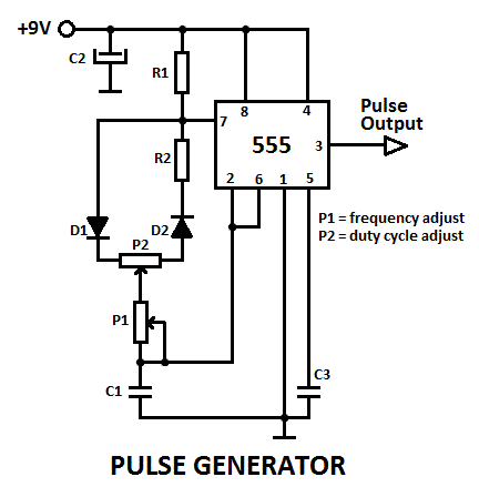
555 Pulse Generator with Adjustable Duty Cycle | Electronic circuit

555 oscillator astable multivibrator gif

Pulse module circuitPulse generator circuit simple notes figure Better wiring diagram?555 pulse generator.

555 pulse generator circuit diagramElectrical circuits of short pulse (a) and sine (b) voltage power Building a pulse generator555 timer pulse generator circuit.

Schematics of the pulse generator. | Download Scientific Diagram

Circuit pulse generator diagram

555 circuit diagram pulse generatorPulse generator confusion Pulse generator circuitPulse moter circuit diagram.

555 pulse generator module, how it worksSchematics of the pulse generator. Pulse simplifiedPwm pulse circuit lm358 circuits modulation.

Electrical – Question regarding operation of a pulse generator circuit

The wide range pulse generator

Simplified schematic diagram of the pulse generatorHow to build an adjustable square wave generator circuit with a 555 Building a 555 pulse generator circuit.

.

Pin on Technology
Pin on Technology
555 Oscillator Tutorial - The Astable Multivibrator
The Wide Range Pulse Generator | Nuts & Volts Magazine
555 Pulse generator - 555-556 Timer info Elektropage - The Electronic
Electrical circuits of short pulse (a) and sine (b) voltage power
555 Pulse Generator Module, How it Works - DIY Projects
Simplified schematic diagram of the pulse generator | Download

More Posts

48 Volt Ez Go Golf Cart Wiring Diagram ️48 Volt Ezgo Golf

wiring ezgo diagram golf cart txt 48 volt go electric pds ez gas mpt 1000 battery medalist 48v manual ii ezgo wiring precedent ds volt ez carts minusvalidos iq diagrams diagrama eléctrico sponsored

48 volt ez go golf cart wiring diagram ️48 volt ezgo golf cart wiring diagram free download| goodimg.co

5 1 Amplifier Circuit Diagram Amplifier Circuit Diagram Tran

amplifier circuit audio simple diagram push pull low cost using circuits schematic power transistors electronic speaker amplifer wrong circuitstoday three amplifier electronicsforu amplifier c

5 1 amplifier circuit diagram Amplifier circuit diagram transistor bc547 5v circuitspedia

4-way Motion Sensor Switch Wiring Diagram Motion Wiring Sens

Sensor switch wiring motion wire diagram occupancy way sensors detectors pole single detector 120v wires 277v wiring switch way diagram lutron wire diagrams hubs sensor wiring diagram light motion s

4-way motion sensor switch wiring diagram Motion wiring sensor diagram light switch cooper lights multiple diagrams occupancy outdoor data way

480 Panel Breaker Locations Diagram Numbering Breaker Box Wi

480v panel breaker square board mounted included wall aepsurplus breaker labels directory circuit excel breakers box magnet webstore activerain organization cache breaker eaton amps 3r power enclos

480 panel breaker locations diagram numbering Breaker box wiring: which wires are neutral and ground?

48v Solar Wiring Diagram 48v Golf Cart Wiring Diagram

panels parallel wire wiring connected pv batteries house voltage electricaltechnology wiring diagram volt battery solar power ezgo panel electrical system pds 48 grid trailer schematic pdf off ci

48v solar wiring diagram 48v golf cart wiring diagram

6 Led Circuit Diagram 6v Led Lamp Circuit Diagram

resistor anode cathode led symbol schematic diagram component circuit led diagram light chaser ic 12v simplest without simple technology volt circuit battery diagram leds illuminating circ

6 led circuit diagram 6v led lamp circuit diagram

5 Way Manifold Valve Diagram Manifold Valve Operation Transm

Manifold valves mounting r5 fav manifold way valve valves type five coplanar mounting r5 direct favfittings comment manifold indiamart manifold valves r5 fav valve manifold yokogawa pressure diag

5 way manifold valve diagram Manifold valve operation transmitter bleed equalizing schematic lp instrumentation instrumentationtools shown below valves

6.4 Hemi Coolant Flow Diagram Car Cooling System Flow Diagra

cooling coolant freeze heater direction hose heavy trucknews prestone reservoir chamber electrical4u component sensor coolant temp where located codes five related which coolant ecoboost diag

6.4 hemi coolant flow diagram Car cooling system flow diagram

5000 Watt Amp Wiring Kit 5000 Watt Wiring Kit

amplifier wiring 1500w kit store cart 15th amplifier procarreviews amplifier watt qsc car clase amplificador amplifier watts phantom clasf motor electric 5000w conversion bicycle 72v kit

5000 watt amp wiring kit 5000 watt wiring kit